A Technical Insight into UMD Racing Team’s Driverless Pipeline — Powered by MYBOTSHOP
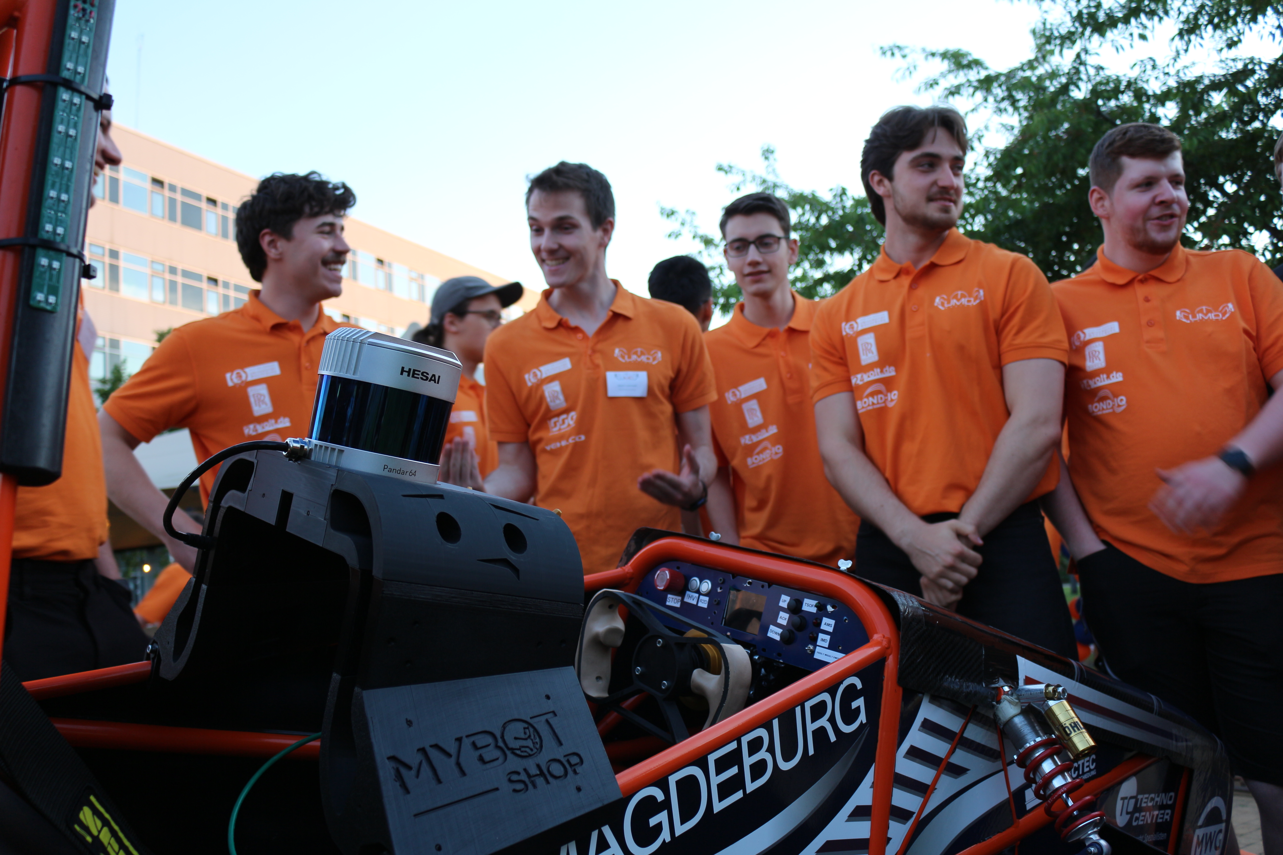
In the Formula Student Driverless Competition, the goal is to autonomously navigate previously unknown track layouts across multiple disciplines with maximum precision and the best possible lap times. While our team previously relied on a pure vision pipeline, we are now ushering in a new era. Thanks to the generous support of MYBOTSHOP, we are integrating the Hesai Pandar 64 LiDAR sensor into our perception system—a technological milestone for the performance and safety of our autonomous race car.
This year, UMD Racing is developing and building our fifth-generation all-electric race car, designed for both manual and autonomous operation.
Previously, our Autonomous Driving System relied on the data flow of a stereo camera architecture combined with power-efficient FPGA evaluation. A pre-trained neural network (NN) detected track cones in 2D image space, while depth information was estimated by matching disparities between both camera images.
Although this system provided a solid foundation, it reached its physical limits at the extremes: changing lighting conditions, shadows on the asphalt, and decreasing depth estimation precision at longer distances presented significant challenges.
Using depth information, the track layout can be reconstructed, allowing us to derive a driving path formatted as sequential trajectories.
LiDAR Sensor for Redundancy and Geometric Ambiguity
With the support of a Hesai Pandar 64, we are transforming this approach into a Unified Perception Pipeline. The LiDAR sensor offers crucial advantages that were previously out of reach with our camera-only vision pipeline:
-
Active 3D Perception: Independent of ambient light, the sensor uses 64 laser channels to output a high-precision point cloud from which the exact 3D coordinates of track boundaries are extracted. This eliminates the geometric ambiguities of traditional camera systems—especially at high speeds and tight cornering radii where cones tend to visually merge.
-
More Reliable Localization: While cameras only cover a limited field of view, our system now monitors the entire surroundings. This enables more stable localization via SLAM (Simultaneous Localization And Mapping), as cones can be continuously tracked even while cornering.
Beating Latency with FPGA Determinism
Processing the massive data rate of the Hesai sensor presents a major technical hurdle. To minimize "sensor-to-planning" latency, we rely on a Kria Board equipped with an AMD/Xilinx Zynq UltraScale+ MPSoC.
Instead of burdening the CPU with pre-processing millions of data points, we utilize the chip's programmable logic (FPGA). By performing coordinate transformation and ground plane removal (filtering out unusable road surface scanned by the LiDAR) in parallel, latency is reduced from milliseconds down to the microsecond range.
In the clustering process, hardware-accelerated algorithms allow us to group relevant points into objects with virtually zero delay. This enables us to maintain a stable environmental map even under lateral accelerations exceeding 2g.
Such a high-performance sensor demands an adequate mounting solution on the chassis. We engineered a vibration-isolated bracket that positions the sensor inside the aerodynamic flow while shielding it from harsh operational shocks. Currently, we are developing the software integration to fuse the LiDAR’s depth data with the vision pipeline's color information—creating a perfect symbiosis of semantic understanding and geometric precision.
From Sensor to Wheel: Our Powertrain
The best cone map and the most precise trajectory are worthless if the vehicle cannot reproducibly execute calculated targets. The powertrain is therefore a direct extension of our perception pipeline, tightly integrated with the safety and control architecture during autonomous operation.
| Parameter | Value |
| Vehicle Mass | 250 kg |
| Wheelbase | 1550 mm |
| Rim Size | 13" |
| Drive Concept | Pure Rear-Wheel Drive with Chain Drive |
| Gear Ratio | $i = 3.83$ |
| Traction Limit per Axle | 2400 N |
| Nominal Battery Voltage | 600 V |
Architecture
Our high-voltage topology follows a classic layout: 600 V Battery $\rightarrow$ Pre-Charge Circuit & Main Contactors $\rightarrow$ Inverter $\rightarrow$ Electric Motor $\rightarrow$ Chain Drive $\rightarrow$ Rear Axle.
In parallel, two galvanically isolated low-voltage networks are powered from the HV battery via a custom-developed DC/DC converter:
-
The 12 V network powers low-voltage consumers (contactors, solenoid valves, sensors).
-
The 48 V network powers the computing units of the driverless pipeline, including the Kria Board and Pandar 64.
This isolation allows efficient power delivery to the computing hardware while maintaining an established 12 V infrastructure for safety-critical actuators.
We use a UniTek BAMOCAR inverter and an EMRAX 228 motor. Both communicate with the Vehicle Control Unit (VCU) via the CAN bus, which acts as the interface to the autonomous computing unit.
Motor: EMRAX 228
The EMRAX 228 is an Axial Flux Permanent Magnet Synchronous Motor (AFMSM)—a design where magnetic flux runs parallel to the axis of rotation. This results in a characteristic disc-shaped geometry (228 mm diameter by 86 mm width) offering three decisive racing advantages: exceptional power density (109 kW peak at just 12 kg weight, approx. 9 kW/kg), high torque at low RPM (230 Nm peak), and an extremely short axial length that saves valuable packaging space in the tight rear section.
We deploy the liquid-cooled High-Voltage variant. Its nominal 680 V rating pairs optimally with our 600 V battery pack, delivering 53 kW of continuous power to provide sufficient thermal headroom for demanding endurance events. An integrated KTY 81/210 temperature sensor in the stator windings provides continuous thermal telemetry.
Inverter: BAMOCAR
The BAMOCAR is a digital 4-quadrant servo controller capable of operating the motor in all four quadrants—a prerequisite for regenerative braking. Key technical specifications:
| Parameter | Value |
| DC Bus Voltage | up to 700 V |
| Overvoltage Threshold | 800 V |
| Continuous / Peak Current | 200 A / 400 A peak |
| Switching Frequency | 10 kHz (adjustable 8–16 kHz) |
With a peak rating of 400 A, the inverter is deliberately oversized compared to the EMRAX motor's requirement (~240 A peak). This ensures thermal derating is effectively avoided during intense acceleration phases.
Gear Ratio Design & Mechanical Power Flow
Equipped with 13" rims, the dynamic rolling radius of the tires is approximately 0.228 m. Peak motor torque of 230 Nm is stepped up through a single-stage chain drive ($i = 3.83$, efficiency ~96%) to an effective wheel torque of roughly 846 Nm. This translates to a theoretical drive force of 3710 N.
However, the physical traction limit of the tires is 2400 N. While the motor could theoretically generate an acceleration of 1.5g, tire grip limits us to roughly 0.98g.
Key Validation Finding: Our race car is primarily traction-limited, not drive-limited. This setup guarantees consistent performance across all operating conditions, maintains thermal safety margins at the motor, and provides maximum control authority for our Traction Control system.
On the speed side, a nominal motor speed of 5500 RPM yields a theoretical top speed of approximately 123 km/h—perfectly tailored to tight, twisty Formula Student track layouts. Mechanical power transmission from the motor to the rear differential is handled by a robust chain drive. Operating at >95% efficiency, it tolerates center-distance shifts during quick gear-ratio changes and is structurally superior to a timing belt under peak torque loads.
Autonomous Operation Characteristics
In driverless mode, the mechanical accelerator pedal is absent. Torque setpoints are sent directly from the central VCU as high-frequency CAN frames. The VCU continuously calculates these targets from high-level trajectory control based on the precise cone map and racing line supplied by our Unified Perception Pipeline.
This imposes strict real-time execution constraints: the entire control path must execute completely within less than 50 milliseconds.
Here, FPGA-accelerated sensor pre-processing proves its worth: microseconds saved during point cloud filtering are directly credited to the powertrain's reaction budget. Our setpoint frame clocks at a stable 100 Hz, matched by 100 Hz status feedback from the inverter (currents, RPM, IGBT temperatures).
Braking System: Symbiosis of Pneumatics & Recuperation
Without a driver, there is no foot pressure on the brake pedal; hence, the autonomous braking system was redesigned from the ground up. We utilize a two-stage strategy featuring two independent operating principles:
-
Stage 1 – Regenerative Braking: During normal operation, deceleration is primarily regenerative. The VCU requests negative torque from the BAMOCAR, instantly shifting the EMRAX motor into generator mode. Kinetic energy converts back into electrical energy, flowing with high efficiency into the 600 V main accumulator. This braking method is finely controllable and ideal for smooth, continuous speed adjustments along the calculated racing line.
-
Stage 2 – Pneumatic Actuation (Driverless Emergency Brake System): For hard braking maneuvers—and specifically for safety-critical emergencies—the car relies on a pneumatically actuated system. An integrated 80-bar compressed air reservoir supplies the required energy. An electrically controlled pneumatic actuator depresses the tandem master cylinder, generating hydraulic pressure in the conventional brake system. Actuation occurs rapidly via a solenoid valve powered by the redundant 12 V low-voltage network.
In regular driving, a smart brake-blending algorithm within the VCU combines both worlds: recuperation for maximum energy efficiency, and the pneumatic friction brake as a dynamic supplement during high deceleration demands.
In an emergency (Emergency Stop), the pneumatic stage triggers autonomously and instantly. Concurrently, the BAMOCAR's rotating field enable signal is hard-cut, ensuring zero torque output from the motor immediately. The air reservoir is sized to guarantee at least two full-stop maneuvers from top speed even under a complete high-voltage system failure, fulfilling the stringent requirements for an independent Emergency Brake System (EBS) per official FS Driverless regulations.
Researching the Future of Mobility
For us, this project is far more than an academic competition. It is an active, practical contribution to research on advanced perception sensors for complex real-world scenarios and their low-latency integration into autonomous systems. In modern production vehicle development, data redundancy and the intelligent fusion of camera, radar, and LiDAR data are considered the true key to safe Level 4 and Level 5 autonomous driving. Optimizing these sensor fusion algorithms under extreme racing dynamics yields valuable, scalable insights for tomorrow's automotive industry.
Partnering for Progress
In a resource-intensive, high-tech environment like Formula Student Driverless, we fundamentally depend on strong technology partners who share our vision and provide access to top-tier hardware. Thanks to the generous support of MYBOTSHOP, we have the unique opportunity to research tomorrow's autonomous mobility and work with industry-standard equipment as aspiring engineers.
We are leveraging this opportunity to redefine the limits of precision and real-time capability in environmental perception, bringing theoretical concepts straight onto the track.
We look forward with great excitement to the upcoming testing sessions and driverless competitions of the 2026 season. The entire UMD Racing team extends our heartfelt thanks to MYBOTSHOP for their trust in our technological vision and excellent collaboration!